

General Lou
-
Posts
633 -
Joined
-
Last visited
-
Days Won
87
Content Type
Profiles
Forums
Gallery
Blogs
Events
Articles
Store
Downloads
Posts posted by General Lou
-
-
Stage 29, suspension:

Firstly, I take the assembly from stage 28 and rest it on the chassis whilst I connect the propeller shaft:
Next, I use the two smallest pins to connect the arms to the arm holder:
Then I place the assembly on to the chassis and screw it in each corner. I connect the arm to the brake section using the last bigger sized pin:
Stage complete. The suspension on this car is wonderful to build!
-
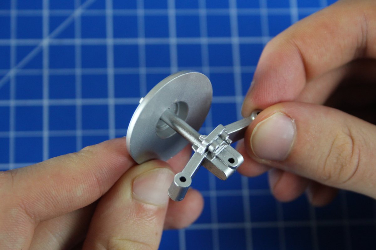
Stage 28, propeller shaft and differential housing:
To start off, I screw the differential housing rear cover on to the assembly from stage 27:
Then I screw on the other half of the differential housing, using one screw:
Stage complete
-
Stage 27, differential housing:
Starting off, I use screws to join the drive shaft connectors to the housing:
Next, using pliers, I connect the drive shaft left and right on to the connectors, by pressing in a pin for each (see how the drive shafts are sloping down which is important to get correct):
And finally, with one more pin, I secure the drive shaft on to the brake assembly from the previous stage:
Stage complete
-
Stage 26, left rear wheel brake:
Firstly, I press the hub cap on to the spinner and put it to the side for now:
Next, I put the wheel hub into the brake disc, then screw on the brake caliper:
Stage complete
-
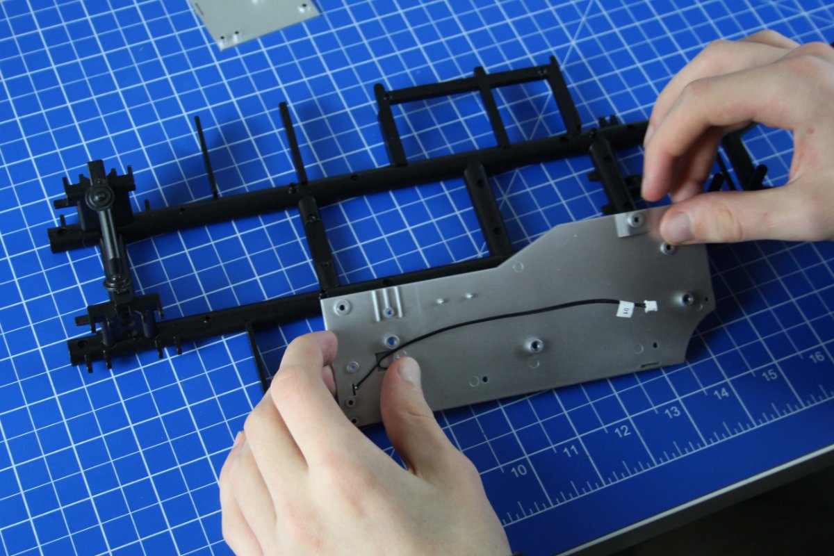
Stage 25, floor panels:
First of all, I align the floor panels with the chassis, then screw them both on:
Now that the panels are in place, I can get my engine and place it on the chassis and hold it there with 2 screws:
Stage complete
-
Stage 24, brakes:
Firstly, I put the wheel hub through the brake disk, then screw the brake caliper over them:
Next, I get my wheel and place the brake assembly into it, then screw it on from the other side:
Finaly, I push the hub cap on to the spinner, then drop it in the wheel and let it magnetise to the screw:
Stage complete

-
On 1/9/2021 at 2:51 PM, Truden said:
Bonjour, J'ai un petit souci avec l'étape 16 du pack 3. Les images ne s'affichent pas, je ne peux les voire. Cordialement, Guillaume
Salut, je ne sais pas ce qui ne va pas, mais c'est corrigé maintenant. Merci d'être patient.
-
On 12/6/2020 at 10:32 AM, Pierre said:
Hello
attention the closing plate of the gearbox is in the wrong direction
You are absolutely correct! Well spotted 👍. We will update the download instructions. Luckily it is an easy fix, just loosen the gear box and swap it round:
-
 1
1
-
-
Stage 90, rear lights:
To start the final stage of this pack, I screw the gas pipe holder on to the back:
Next, I assemble the Shelby emblem and also screw it on to the back:
Then I place build the rear left and right lights and use the cable clips to hold down the wire:
Pack complete
-
Stage 89, rear body section:
Firstly, I use 6 screws to connect the rear section to the back of the car:
Next, I screw both of the trunk hinges on to the trunk, then place them into the car and secure them with the hinge brackets and a screw each:
Stage complete
-
Stage 88, trunk lid and Shelby emblem:
Firstly, I screw the trunk lock on to the trunk lid:
Then I push the Shelby emblem on:
Stage complete
-
Stage 87, hood pins and LEDs:
Firstly, I screw the two horns on to the front of the car, then the centre light bracket goes on (even though the Super Snake has no lights here) and I also use pliers to push the two hood pins in place:
Next, I push the LEDs into the headlamps, then use a bracket to secure the loose wire:
I now push the other two loose LEDs into the lights, then drop in the fog light lenses and gently bend the wire flat so that the lights don't get pushed out when the front facia is joined with the car:
Next, I join the front facia to the car. Before it goes on, i thread the wires through these holes, and then secure it with the screws:
I take the side wire clips, and use them to hold the wires down along the side of the car's interior. Then I put the hood pin plates on to the hood, and place lanyards with lynch pins on the front, and using pliers to make a hook so they don't fall out:
Stage complete
-
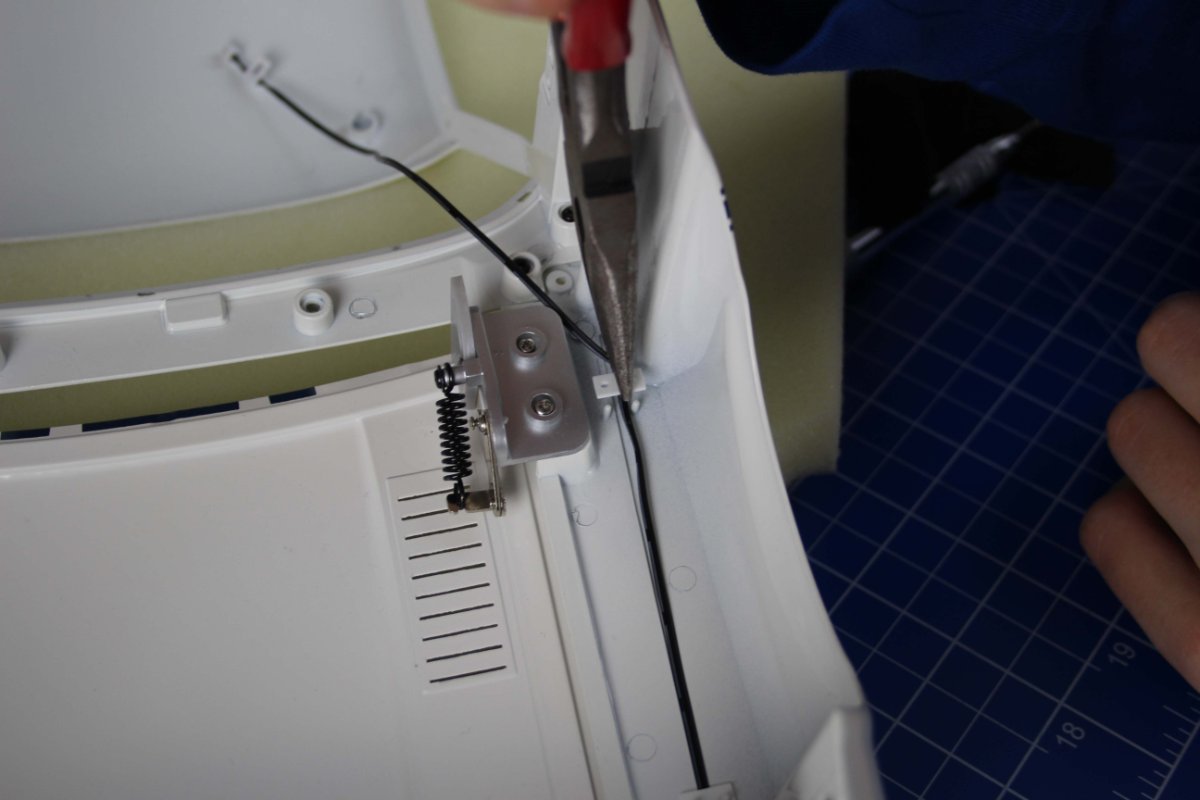
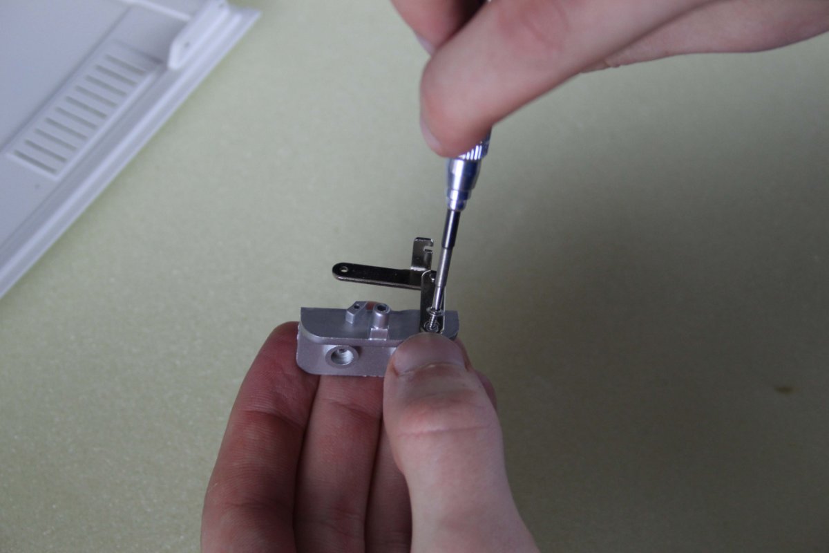
Stage 85, joining the hood:
Firstly, I screw a hood hinge bracket on to the hood, then I screwed a hinge to a hinge support. (All the rights pieces go together and the left ones go together separately):
Next, I join the hinge+hinge support on to the hinge bracket, then connect the end of the hinge to the hood:
The hinge spring goes on. I use pliers because the spring is very resistant to being pulled. Once the spring is in place, i hold it there with a screw:
Finally, I assemble the other hinge and screw them both on to the hood, then to the car:
Stage complete
-
Stage 85. Hood and grille:
Firstly, I bend the two tabs in the holes on the grille, so that I can push the Shelby emblem into the grille. Then If the Shelby emblem does not stay in by itself, you can use some pliers to squeeze the tabs against the emblem like i did:
Next, I bend the tabs on the outside of the grille backwards so they point away from the Shelby emblem, then I push the grille into the grille frame and bend the tabs flat again to hold it in place:
Finally, I screw the grille on to the front fascia:
Stage complete
-
On 12/2/2020 at 6:04 PM, john hunter said:
There looks to be screw holes for the roof lining or is it a push fit?
I believe it is a push to fit, to create a nicer finish. The roof lining doesn't go on in this pack.
-
Stage 84, side scoops:
In this stage, I screw the side scoops on to the car. Only the correct scoop will fit into its correct position nicely, so it is easy to get them in place correctly:
Then I screw the rest of the side scoops on:
Stage complete
-
Stage 83, main body:
WARNING: The gaurdsman blue stripes on the roof will scratch if the surface is rough. Place it on some foam like i have in this picture. I leanrt this the hard way, so be Very careful when you have it upside down:
The second thing to do is to attach the front fender on to the main body with the screws supplied:
Stage complete
-
Stage 23, tire:
Firstly, I boil a kettle and use the hot water to soften up the tire. I leave it in the water for 5 minutes:
While the wheel is softening in the water, I screw the outer rim to the wheel assembly from the previous stage:
Once the 5 minutes are up, I place the tire on to the rim:
Pack complete
-
Stage 22, wheel:
This stage is in preparation for the tire, so it is failry quick. I screw the inner rim to the outer rim using 4 screws.
Stage complete
-
Stage 21, chassis and wishbone mounting:
Firstly, I screw the rear chssis part on to the chassis assembly using 4 screws:
Then I screw the rear suspension wishbone mounting on using an other 4 screws:
Stage complete
-
Stage 20, chassis:
Firstly, I join the suspension support and chassis to the other chassis piece:
Now I have 2 chassis assemblies. I place one on top of the other, and screw them together:
The top cross members that come in this stage, are screwd on to the chassis. The cross members are different so i make sure i have them in the correct positions:
Stage complete
-
Stage 19, continuing the chassis:
This is a fairly simple stage, where I screw the suspension support from the previous stage, on to the chassis piece from this stage:
Stage complete
-
Stage 18, front suspension support:
In this step, I screw the cross member support on to the chassis assembly, over the previously attached cross member support:
Next, I push the horns on to the front suspension support. I chose to glue these on for additional support:
Stage complete
-
Stage 17, more chassis:
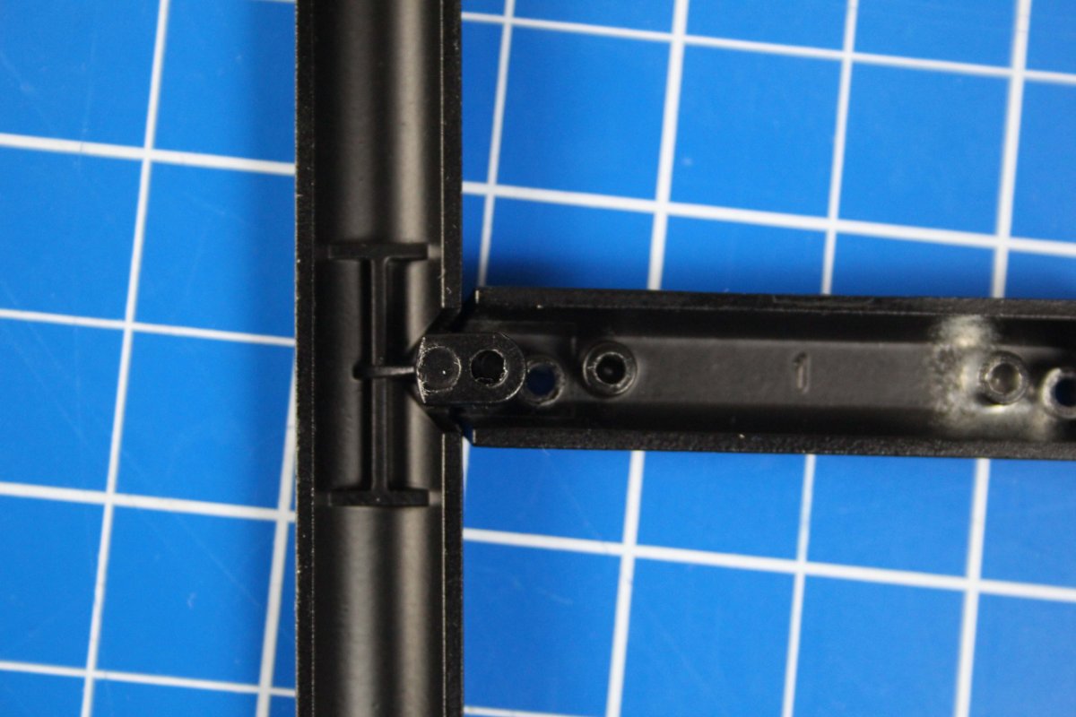
Just like this previous stage, I screw the cross members on to the chassis piece. Number 1 on the left image, has slightly offset screw holes. this image shows the correct way of assembling:
Now this assembly join to the assembly from stage 16 like so. Again, make sure all the numbers are facing the same way as eachother:
Stage complete


Shelby Cobra Pack 4 - Stage 30
in Pack 4 - Shelby Cobra Official build Diary
Posted
Stage 30, suspension:
Firstly, I use a pin to secure the shock absorber cylinder in place. You can find out if you are using the correct pin because it should not be too long or too short, it will fit perfectly.
Next, I use another pin to connect the piston to the left rear lower arm. Once I have done this, I put a spring over the piston cover on the car, then the left rear lower arm fits into the chassis and brake.
I now put pins through the sections where the left rear lower arm fits to the chassis and brake:
Stage complete