

General Lou
-
Posts
633 -
Joined
-
Last visited
-
Days Won
87
Content Type
Profiles
Forums
Gallery
Blogs
Events
Articles
Store
Downloads
Posts posted by General Lou
-
-
Now I'm getting some large components done and the cabin is coming to shape uo with some structure!

The rear section is screwed into place.
-
As mention in the previous post, I am now doing the second half of the center console and also adding the floor mats.
Similar to the stage 43, I've screwed the second half of the floor to the center part
The floor mats are slightly different but its straightforward putting them into the correct side of floor
-
Moving on to the center console...
This all fits together quite neatly with a few screws.
I've put the electric cable holder inlace which will be need later for...you guessed it holding cables!
I will be completing the second half of this in the next stage
-
Continuing with adding more detail the dashboard
I found it best to use a sharp blade to peal off the stickers. using fingers just bends the sticks or removes the glue onto your fingers, keeping the sticker on the tip of the knife allows me to position correctly, keeping in Mond that the dials are big enough to read so they need to be fitted the correct way up!
Notice how the speedo looks back to front - this is how it was on the real Cobra, though I don't know why they did it like that.
Following putting on all the stickers I've then put the glass onto the chrome and then both of these fitted onto the black plate:
I then put all of this into its housing which also contains an electronic switch.
Screw it all together and then its stage completed

-
Getting to some fine detail in this pack with the dash...
I put the two plates into the back of the dashboard so that the metal colour comes through to the front
The Shelby name plate has some great detail of including the Cobra badge and Carrol Shelby's signature
After adding the steering column bracket, I added some of the buttons and switches to the dash. I'm liking the fact that you can read the wording on the switches.
-
Front fenders & airflow
The left and right fender liners are screwed in
I've attached the airflow intake and it is screwed in two places from this side...
...and then Ive turned it over to put the other two holding screws in place.
And here is my build at the end of Pack 5!
-
Next is the front right suspension.
First, the shock absorber cylinder is attached to the main body and I used pliers to get the pin to fit fully. Pins are used to allow movement in the mechanisms.
The lower part of the assembly is then put together ready to attach in a few steps' time.
Adding the control arm...
Then sliding on the suspension spring...
Connecting piston and cylinder (sorry its out of focus a bit!)...
And finally attaching the whole thing with the two pins underneath...
And now the fourth and final wheel is attached!
Stage complete & looking good!
BTW, don't worry if the front wheels appear wobbly, they still need the steering mechanisms attached which will hold them securely together.
-
The first part of this stage is to fit the piston, I then secured it in place with a pin, tightening with pliers.
The pins allow the cylinder to move.
Next I worked on the shock absorber, by attaching the lower control arm, again with a pin.
Once completed I then connected the control arm, agin with pins to give it movement.
The spring slides on to the piston which then slides into the cylinder that I just added to the chassis. Then the assembly is secured in place with two pins which I needed to use pliers to secure.
The wheel slides over the rodent again another pin is used to secure it in place.
The first of the front wheels is now in place!
-
Another 2 wheel assemblies!
First I put the wheel together which simply was screwing the inner rim into the outer rim and putting the two halves of the outer rim together.
Next I bolted some water and let the rubber tire soak for 5 minutes to make it pliable and then its easy to handle to force it around the rim.
I added each wheel onto the hubs and then screwed them in place. Each screw is the covered over with a spinner
And now I have the rear two wheels in place!!!
-
Attaching the floor panel at the rear of the car.
The rear floor panel sits comfortably on top of the chassis
...on the under-side the panel aligns with screw holes
There are two sets of screw holes to secure the panel to chassis.
All done!
-
I love the suspension on model cars - giving them the 'push' test to see what the suspension is like!
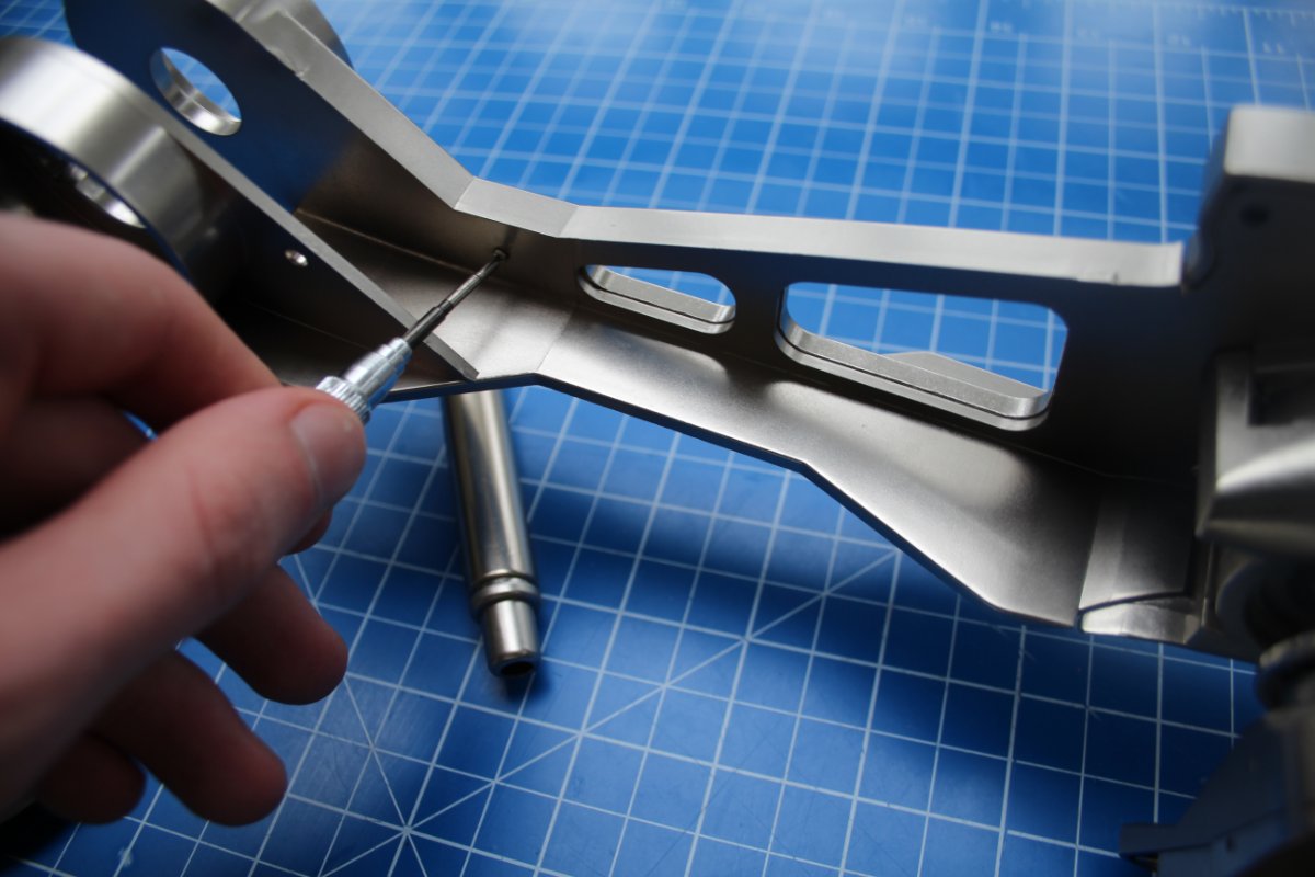
The shock absorber piston is held in place with a small pin. The end of the pin with the ridges is the final end to be inserted. I used pliers to then force the pin in fully.
Similarly, I used the pliers to push the second pin in place when attaching to the suspension assembly.
You can see the pin in place here:
I then added the spring onto the piston and fixed it all together:
I secured the wheel hub in place with pin, again fully fitting it with pliers:
Stage complete!
-
Oh sorry!
So, our models are transported across borders with a "model kit" duty category, which means they should attract zero % duty. ie they are not liable for import duty. Therefore US to Canada has 0% duty.
-
 1
1
-
 3
3
-
-
Building toe number 3/5, and some more of the lower leg:
I'm sure you know how the toes are built by now so here is the third toe complete:
Next, I screw on the leg part to the already built assembly from the last stage:
Stage complete
-
This is the beginning of stage 97, where I create the second toe and lower leg. Here are the parts:
I start with the toe. The pins are hard to push in because this allows them to remain ridged, and will stop the toes from flopping.
I then put some glue on the lower leg and slide the sleeve down the ridge to the end. Then I screw this part on to the base of knee joint:
Stage complete.
-
Stage 96, knee cap and toe:
Building the toes is fairly similar to the fingers, as all I did was line up the parts and push in some sleeves and pins to hold the parts together. One thing to note is that the foot bones are not straight, meaning there is a certain way they go on (one end is smaller than the other and they are slightly angled):
Next I stick the two knee cap plates together and then glue it on to the knee joint like so:
Finally, I add a joint circle on to the bottom of the knee with some glue:
stage complete
-
Stage 95, building of the knee joint:
I start making the knee joint by gluing two of the black circle pieces on to each side of the knee joint. One of the joint circles is from stage 86 which I kept safely from being lost. Next, I screw the tendon on to the knee joint and then use three screws to join on the bottom knee joint part:
Now we put the knee on to the T-800. I start off by putting the tendon into the muscle and lining up the knee joint so that I could put the 2 parts either side of the knee (first image) in place, which are from stage 94 and 92:
Moving on to the foot, I screw on part A of the ankle parts with a screw and washer. Next I push the second ankle piece underneath. A lot of pressure was needed to pop it in:
Stage complete
-
In this stage, I join the muscle and tendons to the leg:
Firstly, I glue an inside joint on piece to the knee joint, then put this part aside, for now:
Now I make another tendon, by screwing a washer on the end and dropping a nut inside. Then I take the thigh muscle and screw it on to the back of the T-800:
Now I take both of my tendons which I built, then push them inside the two thigh muscles on the left leg. Once they are in place I join them together with a screw at the bottom:
I finish off by screwing the two hemisphere parts on to the top of the foot:
Stage 94 complete
-
Welcome to stage 93, where I build the build some foot and another muscle:
I start off by gluing around the sides of the muscle cap and then slot it into the thigh muscle. You really don't need much glue for this part:
Next, I drop the inner thigh inside; then I close it off by gluing the muscle connector in place:
To finish this stage, I screw the two foot parts together like this:
Stage 93 - complete.
-
Stage 92, knee and foot:
Firstly, I place some glue on the black circle and put it on to the knee joint:
Then I screw a washer on to the end of the tendon like so:
Now for the foot, I screw three ball joint pieces on to it and place it aside for later:
Finally, I screw the thigh muscle on the Terminator, mirroring the right leg:
Stage complete
-
Stage 91, left thigh muscle:
In this pack, I start the assembly of the left leg; beginning by gluing the muscle cap on to the thigh muscle:
Next, I place the inner thigh muscle into the thigh muscle, then close it off by gluing the muscle connector on:
Stage complete
-
Stage 90, thigh:
I take the leg plate and use three of the small screws to screw it on to the thigh. The screws are awkward to screw in, so I had to bend his leg right back:
Now I screw in the leg piece from stage 89, and then the pack is complete!
-
Stage 89, hip:
I start off this stage by pushing the insert into the leg tube:
Next, I finish off the hip by using my hex key to screw in the last cover over the joint:
Stage complete
-
Stage 88, hip joint:
Starting off by placing the casing and joint inside the hole, then lining it up with the pelvis:
Next, I place in three more casings in the joint, then use four screws to hold the leg on:
With the thigh on, the stage is now complete:
-
Stage 87, left thigh:
I put some glue into the four holes in the thigh and then drop a nut in each of them:
Then I put some more glue on to the joint piece from the last stages and slot it in above the four nuts:
Stage complete


Shelby Cobra Pack 6 - Stage 46
in Pack 6 - Shelby Cobra Official build Diary
Posted
Back to the small fiddly bits! its time to add on the gear stick and the hand brake
I put he two lower parts of the gear stick together, turned the whole thing over, keeping it in place so it doesn't fall out, and screwed it in place from underneath
The U-bar (Im sure I will find out what that is for later!!😃) was just pushed in and similarly screwed in from underneaths:
Check out the detail on top of the gear stick, you can actually read all the gear numbers (sorry not too clear on my photo - I'm talking about in real life).
I've then added the hand brake next to the gear stick, it just pushes into place quite easily.