

General Lou
-
Posts
633 -
Joined
-
Last visited
-
Days Won
87
Content Type
Profiles
Forums
Gallery
Blogs
Events
Articles
Store
Downloads
Posts posted by General Lou
-
-
Stage 85, connecting the hand to the arm:

I start off this stage by screwing the three washers on to the three shafts like this:
Next, I place some glue on to the muscle connectors, and then I use my tweezers to place them on to the hand:
Now the hand joins with the arm. Firstly, I inset the three shafts into the forearm, then thread the spring pieces through four holes on the base of the hand:
I then push the shaft and the balls on the hand together, to create the wrist joint. After this, I put some glue on the springs and pull them on to the muscle connectors that I attached at the start of this stage:
Stage complete
-
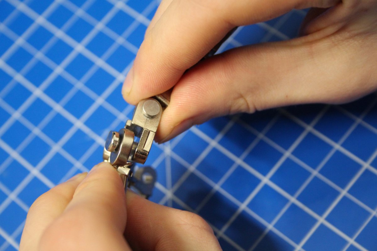
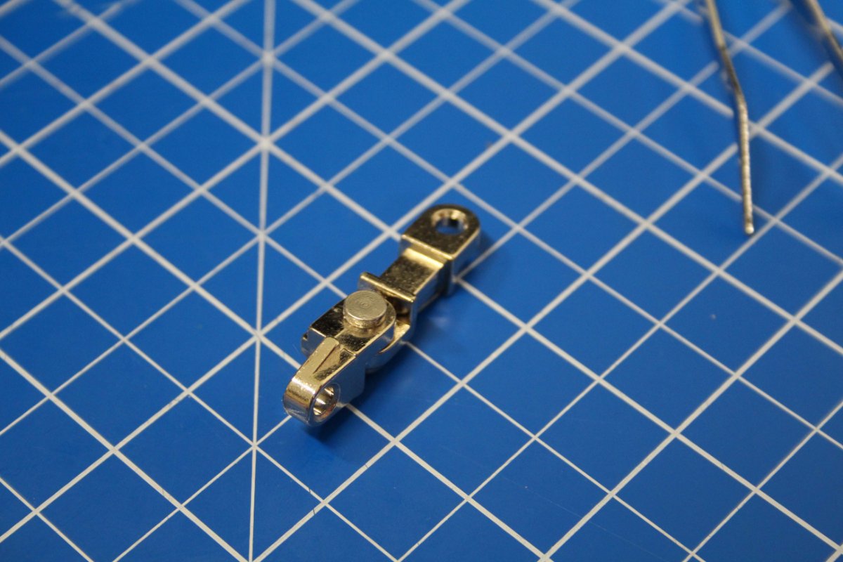
Stage 84, thumb:
The thumb is slightly different to the fingers, however the process is the same. I build the thumb then screw the two joint pieces together:
Now I screw the thumb on to the hand and apply some glue to the big ball joint, along with a screw to attach it to the hand:
Hand complete
-
Stage 83, finger:
Here I build another finger. I have built 8 already so I do not include any more photos of me building it as you have probably seen enough 🙂
Then I screw the three ball joints for the wrist, underneath the hand:
Stage complete
-
After 99 stages, here it is the final one!
The finishing touches.
I screwed the rear licence plate directly onto the valance
And then I screwed the whole assembly onto the back the Super Snake.
Across this, and hiding all the screws goes the rear chrome bumper
Moving on to the front, the licence plate screws straight into the body
And there it is the final piece is on!
By the way, although the 'Snake 67' is a cool plate, you will soon be able to get individually personalised ones for you - watch this space (or at least the Agora home page!)
So here is my 1967 Shelby Super Snake. It has been a really enjoyable build. I hope that you liked the build diary!
You will be glad to know that the lights, horn and sounds all worked first time for me!!!! now on with my next one.....! 😃

-
With stage 99 you get the fog lights and rear valance, but first I need to put the body shell onto the chassis.
Some of the wires are not very long so I found it easier to put a bit of foam across the inside of the car and then rest the body on top. This made it easier to handle and didn't run the risk of pulling the wires out. All the wires are numbered at both connecting ends so it was just a case of matching them up and plugging them together.
Once all the wires are connected I then dropped the body onto the chassis. Make sure everything lines up and it all needs to click into place. the first time I tried I hadn't got it pushed in enough and this meant that when it came to screwing it in the screws wouldn't bite.
As you lower it, and before it fits together you need to make sure that all the wires in the engine compartment are tidied up and hidden away at the back in the compartment that gets completely hidden.
I turned the model upside down on my lap to screw in the screws that hold it all together. This way you can avoid damaging the aerial
Now I prepare the fog lights. I pressed the glass into the casement (no need to glue) and then screwed them in from the back.
And now onto the very final stage.....
-
Adding the sun visors and mirror.
The sun visors just push into place. But make sure you put them on in the right way. There is a orange sticker with warning writing on, these should be readable by the driver and the passenger when the sun visors are in the 'up' position.
I pushed the two parts of the rear view mirror into place. they did not need gluing. There is only one way that they can fit together. Tho whole assembly is then screwed into the headlining between the two visors.
Next I lowered the whole thing into the inside of the body. It was a little fiddly to get it lined up with all the holes. They need to be pressed in firmly for it to sit correctly in place.
I pushed the aerial into its hole and then turned over the car to screw it in position. I found this was best to do by balancing the car on my lap so as not to bend or break the aerial when it was upside down.
Stage complete!
-
Headlining and putting the doors on.
The headlining is stage 96 but you don't do anything with it until stage 98. This stage is putting the doors on.
I found the best way to put the doors on is to have them shut when you screw them in place, this way they are aligned properly. Only one screw needed for each door.
Stage complete
-
Adding the door trim.
Both door trims are attached in the same way. I pushed the upper trim in place first.
Followed by the door sill plates.
On one of them I did find that the hole had some body-paint on it preventing the lug on the sill fitting properly. Be careful not for it as the sill will break before the bodywork does. To fix this I just enlarged the hole with the screw diver by working away the pain. It then fitted nicely
Stage complete.
-
The Rear Window as Alfred Hitchcock would say...!
I found this was a similar process to the front screen. Firstly I rested the window in place and then I snapped on the chrome frame, starting at the bottom of it.
I did also get the aerial at this stage which could go on now, but its not a good idea to put it on yet as the next stages require a lot holding and turning of the body so there is a danger I would snap the aerial. So for now its stage complete.
-
Stage 93, fixing the wipers to the grille.
The two wipers are marked 'R' and 'L' so that you know which one goes in which hole. Once in place I simply screwed them in from behind.
hey presto!
I secured the grille into the body from underneath with two screws, remembering to use foam on the suface to protect he roof paintwork
Stage complete!
-
Stage 91 and 92 are together being the front windshield.
The screen is placed on the body and then the chrome surround snaps into place. I pushed the bottom of the chrome slots downwards into he body first and then the top is pushed firmly until it clicks.
Keep the wipers for the next stage.
-
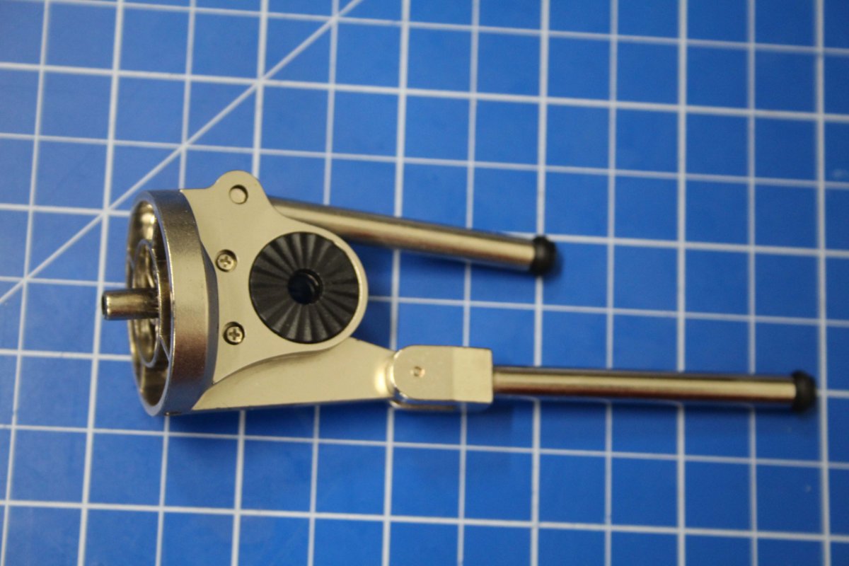
Stage 82, forearm and finger:
I connect the finger that I built from the previous stage with the rest of the hand:
Then I screw another shaft piece on to the middle of the forearm:
I apply some glue on to the black circle and place it in the joint of the upper arm, then place the forearm cover on to the forearm. It sits on there loose until the next step:
Finally, I screw the forearm and the upper arm together, and that's the stage complete:
-
Stage 81, forearm and finger:
Starting off pack 9 with another finger. Here is my three step process of creating it:
After the finger, I screw the shaft and shaft connector to the forearm assembly. This has to be done twice, for each side:
Stage complete
-
Stage 80, forearm:
Firstly, I put some glue into the grooves of the forearm plate, then lay each spring into them:
Next, I screw the springs on to the shaft, then screw the shaft to the forearm joint:
Finally, I connect the second finger with the hand, and then I'm finished:
Pack complete
-
Stage 79, finger and arm
Starting off this stage with building another finger, just like before:
Moving on to the arm, I place a socket liner into it and screw a screw through the metal bar from stage 73:
Next is gluing on another washer:
Now, I put the shafts on the elbow joint into the arm, then screw in the left arm joint piece:
Then I glue the second joint piece over the joint like so:
Stage complete
-
Stage 78, left hand and arm joint:
Firstly, I join the finger from the previous stage on to the hand, using a connector with a plastic sleeve. Then a pin with some glue on it:
Next, I glue the washer on to the shoulder joint. Then I glue the shoulder joint to the arm:
Then I place the shaft from stage 73 with a metal washer between two joint pieces, and screw them together:
Stage complete
-
Stage 77, finger:
This finger is the same as the right hand, so using the same method I assemble the parts with a little glue on the connector pins:
Stage complete
-
Stage 76, continuing with the left arm:
First of all, I place a socket liner into the arm, then rest the circle on the joint assembly inside of it:
Next, I get the two muscle pieces, and second arm piece and rest them on top of the arm from the previous step. I then take two screws and put them into the arm to hold in the muscles like so:
Stage complete. The joint should be rotatable.
-
Stage 75, left arm:
This stage is super quick. I drop the socket liner into the arm, making sure to line up the curve on the socket wall with the curve on the arm:
Stage complete
-
Stage 74, tricep muscle:
In this stage, I build the tricep muscle. The process and mechanics of this stage are very similar to what we have built before. I start by inserting the shaft which then screws on to the cap from the other side:
The final part of this stage is pushing the washer+shaft down the tricep tube:
-
Stage 73, left shoulder:
I start off by screwing the two shoulder parts together:
Next, I place the rubber washer on to the shaft, then screw it through the middle to hold it in place:
Stage complete
-
Stage 72, starting the left arm:
If you have already built an arm, you will be familiar with this process. So to start this arm, I put the shaft piece inside the arm part, then screw the shaft on to the cap like so:
Stage complete
-
Stage 71, the foot:
Firstly, I connect the two foot bones on to the toe joint using a pin and rubber tube, and a screw with a hex key:
Next, I use another pin and rubber sleeve to attach the toe:
Now that I have all of the foot bones built, I join them to the ankle by threading a grub screw through them all, once the holes are aligned:
Then I use the second grub screw and repeat the previous step:
Stage complete, what a fabulous foot!
-
 1
1
-
-
Stage 31, right rear wheel brake:
I build another brake, fairly simple and the same as before:
Stage complete


T-800 Terminator Pack 9 - Stage 86
in Pack 9 - T-800 Official build Diary
Posted
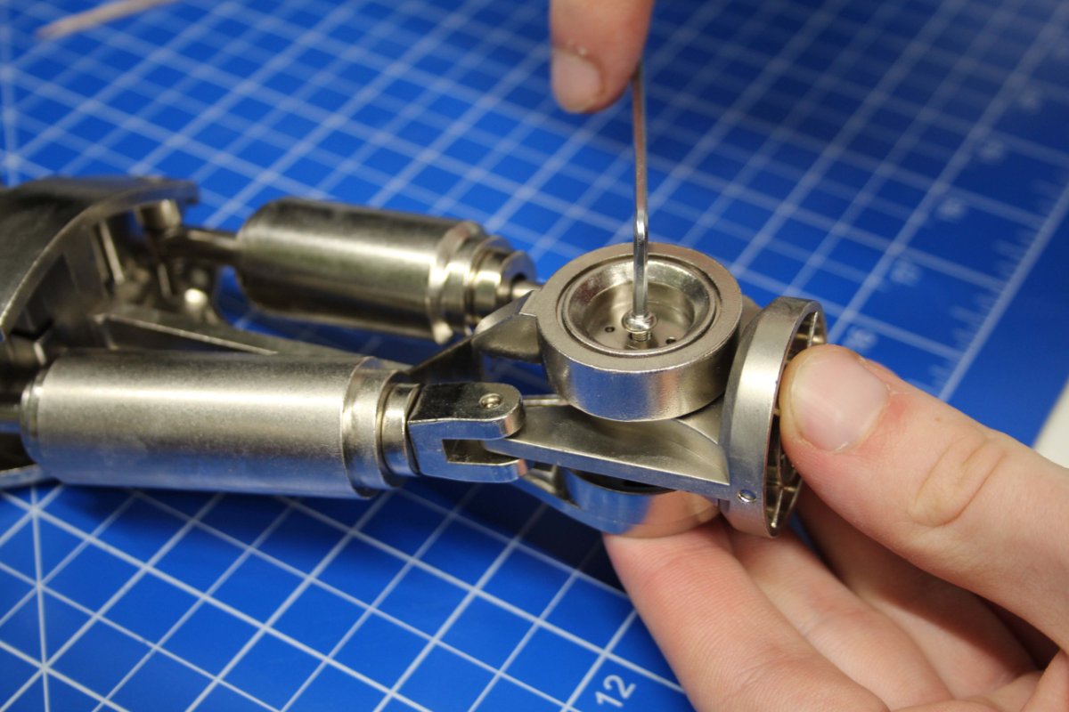
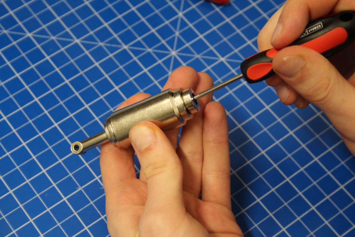
Stage 86, arm joins with shoulder:
Firstly, I push the two leg joint parts together and put them aside for now. Then I apply some glue to connect the washer:
Now for the shoulder. I align the arm with the Terminator and place the shoulder pin through. Now I flip the Terminator on to its front so I can screw in the pin from the back. Notice the blu tack I placed underneath to hold the pin from falling out:
Stage complete