

WonderWoman
-
Posts
109 -
Joined
-
Last visited
-
Days Won
5
Content Type
Profiles
Forums
Gallery
Blogs
Events
Articles
Store
Downloads
Posts posted by WonderWoman
-
-
Stage 4: Assembling the catapults and testing the motor

We start stage 4 by assembling a bit more of the hull section. You simply fix a connector onto the section, making sure the connector is on the right way and fits flush to the hull.
Now we can start to assemble the catapults.
I started by trying to push two axles into two of the wheels. They didn't push in and ended up stabbing my thumb and firing off. Once retrieved, I found the axles only needed to rest in place while I pushed them through each end of the catapult track and secured them in place with another wheel. Once both wheels were on, I could then exert more force by laying the catapult on its side and firmly pushing the parts together.
Then sliding the catapult support over the track was easy. It's a loose fit as it slides. Then making the second track was easy as I didn't have to turn the room upside down looking for lost wheels!
Now for the motor test…
I took the lid off the battery box and installed 3 x AAA batteries. Then, plugged the cable into the ‘Power’ socket on the circuit board, and the cable from the gun turret into the ‘Motor’ socket.
When you slide the switch to ‘ON’ you should hear gun sound and see the gun motion. Anton is now ready to fire with world-leading accuracy and speed!
Stage 4 catapults and motor test complete! Onboard Bismarck, these catapults were actually 32 metres long and could be extended telescopically to 48 metres. They were located amidships and on both sides.
-
Stage 3: the first Arado AR 196 sea plane
Before starting work on the plane, I fitted the lower part of the hull to the hull section from stage 1, screwing the pieces together. When fitting the hull components, I made sure I had a flush fit before placing the screws. You’ve got to keep checking the outside of the hull, and then tighten the screws when you’re happy it looks flush.
Now for the sea plane. The parts for this are super-tiny, so a magnifying glass and tweezers might be useful!
I started by gluing the two fuselage sections together.
Assembling the engine and propeller: the propeller shaft is in the packet of screws if you can’t find it!
I placed the shaft in the engine, then pushed the propeller on the end. I found it easier to do this by holding the shaft in place at the front of the engine with my screwdriver. Once the propeller has been added, you can push the parts together quite firmly, and I found they held without glue, eliminating the problem of too much glue preventing the propeller from spinning. The fit feels quite secure, but if necessary, I'll add a spot of glue if the propeller keeps coming off.
Then the engine fixes to the fuselage. You should check the colours on the underside of the bodywork are aligned correctly.
For this next bit, I needed a magnifying glass – to cut the control lever, pilot’s seat and machine gun off the sprues and then glue them to the cockpit before gluing the canopy on. Let me know how you get on with this! Take a deep breath, and enjoy this moment of surgical precision...
Next – the floats:
The slots in the floats face innermost and the shaped end faces backwards. I started by resting the feet of the side struts in the slots. Then glued the struts into the slots, making sure the strut with pegs on faced forwards.
It's a good idea to test fit the floats to the underside of the fuselage before applying glue. Also test-fit the catapult launch carriage to see how both parts fit into the holes as the holes are tiny and it's easy to get them slightly out of place.
Stage 3 complete! This is a little plane that served Germany well. There's more interesting info about it here: https://airandspace.si.edu/collection-objects/arado-ar-196-a-5/nasm_A19610128000

-
Stage 2: Building ‘Anton’ gun turret
To begin making gun turret ‘Anton’ I cut the two ventilators off the sprues and glued them to the gun turret housing, along with the two ladders. The ventilators are fitted by gluing them (as shown in the instructions) on the shaped end, and then rotating them 180° before positioning in the holes.
Then I assembled the gun barrels, gluing the barrels to the connectors and positioning the ring (so that the ‘L’-shaped notch faces upwards) , the clutch shaft and the tension spring. The parts remained loose during the assembly until everything was fixed at the end with screws. You just have to keep holding everything together as you go.
Next, you turn the gun barrels over so that the notch on the ring faces downwards and slide the barrels through the tubes on the cradle. The spring should reach the edge of the cradle when you push it.
I placed the motor housing in position and then, holding everything together, fixed it together with the screws. I had to keep pushing on the spring to feel it compress but it didn't seem to protrude as much as shown on the instructions.
Fitting and screwing on the motor and mounting was straightforward.
Then the guns were mounted in the turret. I slid the gun barrels through the holes, resting the pins on the cradles on either side of the turret.
The base plate was lowered on top, threading the motor cables through the opening and securing with the six screws – three along each side. I always loose-fit the screws, check the positioning of the parts, and then tighten them.
Stage 2 and Anton was complete.
-
So, let’s get started with stage 1.
I like to start building each Pack by laying out the parts in the same configuration as given in the build instructions. This way, I know asap whether I’ve left any tiny bits in the packaging or fired any pieces across the room as I’ve prised the packaging apart.
I started by assembling the warping winch and the capstan head.
Then I prepared all the parts for fixing to the deck by cutting them off the sprues. A note of caution: I found when I cut the sprues, the pieces easily flew off into oblivion. So now, after moving various parts of furniture to retrieve lost parts, I position my knife, then put a finger over the part to keep it place before exerting enough pressure to make the cut. This way I can keep them under control. If you prefer to use pliers, you can keep hold of the parts as you cut.
I then test-fit the parts and clean off any excess flash from the sprues to check the fit.
Before gluing in the rear group
And then the forward group
Finished. Now I have a good feel for how this build is going to go!
-
As usual on a lazy Sunday morning, when I opened the weekend papers last weekend, I turned straight to the Driving section. There was an article featuring Kiefer Sutherland. His first car was a "... gold, straight-six '67 Mustang"!
He has great taste in cars! It got me wondering – does anyone know of any other famous Mustang owners?


Bismarck Pack 1 – Stage 5
in Pack 01 - Bismarck official build diary
Posted
Stage 5: Starting the anchors with the capstans and anchor chains
As for stage 4, we begin by fixing another connector to the hull section.
Then we add some parts to the upper deck.
I test-fitted the two anchor chain openings and two chain guards before gluing them to the upper deck.
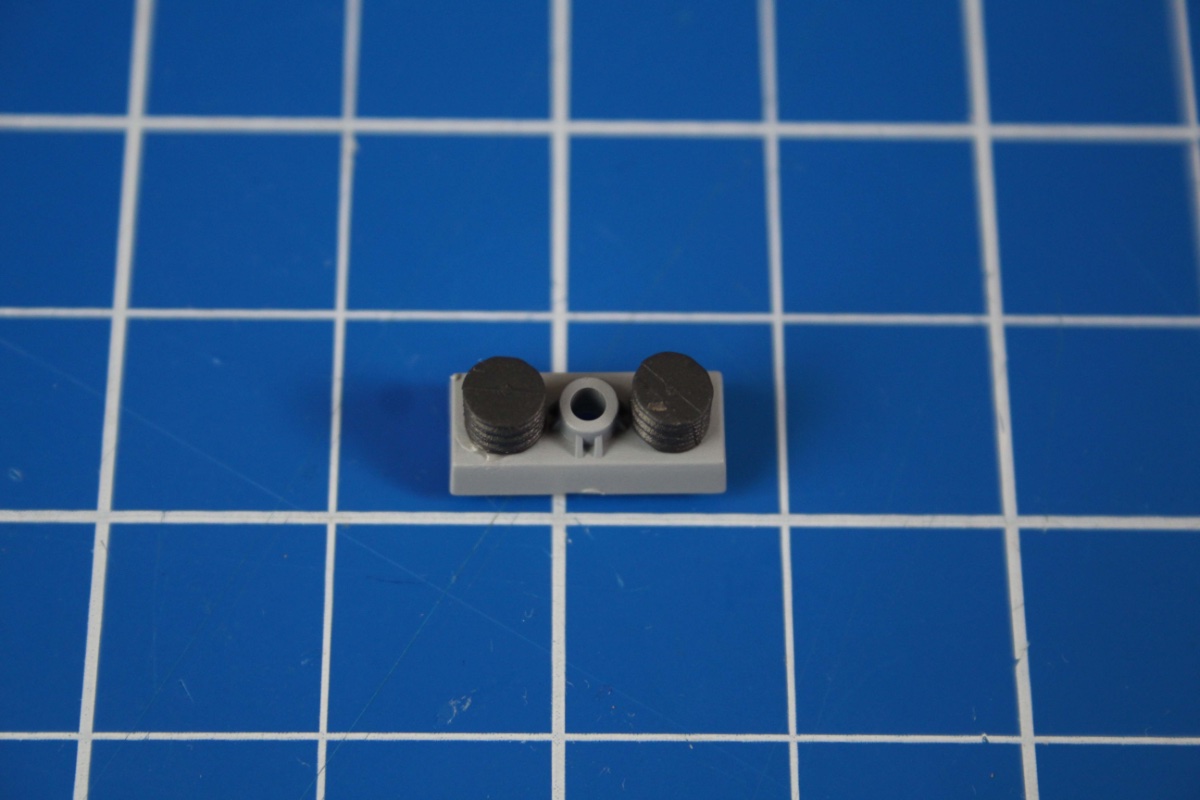
Then to the capstans.
Rather than apply glue to the wheel (as instructed) I applied glue to hole of the shaft before fitting the wheel peg into the shaft. Then turned the shaft 180° and firmly pushed the green drum and the support down the shaft as far as they could go. The process was repeated for the red capstan.
Stage 5 complete!